New products are available now. These products are compatible with Ferrotec’s seals. Click on the following Cross Reference Sheet.
Cantilever Series F1T-***-C***
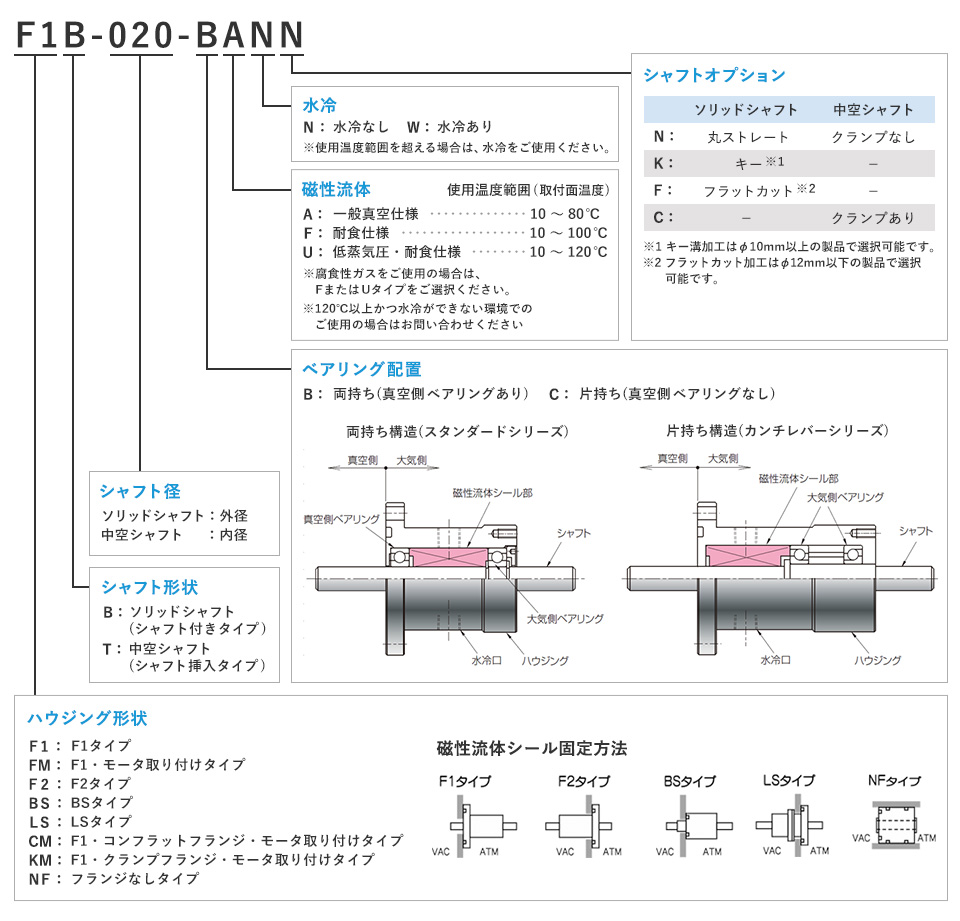
Hollow shaft (requiring shaft insertion)Shaft diameter :40Shaft diameter :50Shaft diameter :75Shaft diameter :20Shaft diameter :25Shaft diameter :30Bearing arrangement :Cantilever (One side)Water cooling:Water cooling
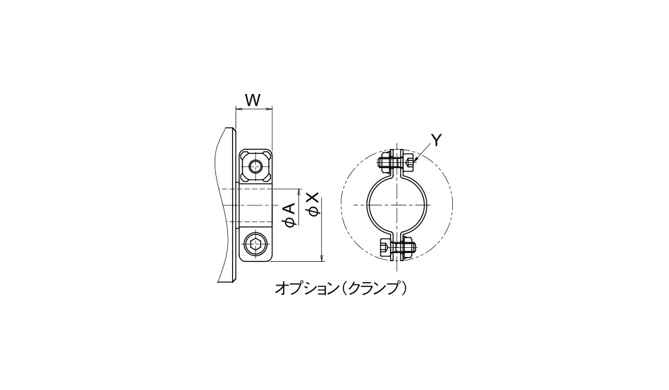
Without clampWith clamp
Without clampWith clamp
This is based on the F1T type, with the magnetic fluid arranged in the vacuum side. This is suitable for active gas applications.
CAD Download
You can use CAD data downloading after making a member account.
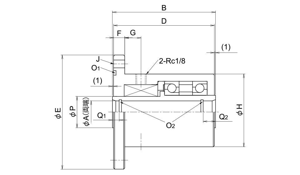
Product Specification
| F1T-020-C | F1T-025-C | F1T-030-C | F1T-040-C | F1T-050-C | F1T-075-C | |
|---|---|---|---|---|---|---|
| Inquiry | Inquiry | Inquiry | Inquiry | Inquiry | Inquiry | Inquiry |
| A [mm] | 20H7+0.021 0 |
25H7+0.021 0 |
30H7+0.021 0 |
40H7+0.025 0 |
50H7+0.025 0 |
75H7+0.030 0 |
| B [mm] | 116 | 118 | 134 | 65 | 65 | 74 |
| D[mm] | 114 | 116 | 132 | 63 | 63 | 72 |
| E [mm] | 99f7-0.036 -0.071 |
109f7-0.036 -0.071 |
114f7-0.036 -0.071 |
128f7-0.043 -0.083 |
138f7-0.043 -0.083 |
179f7-0.043 -0.083 |
| F [mm] | 10 | 10 | 12 | 10 | 10 | 12 |
| H [mm] | 64 | 74 | 80 | 92 | 102 | 143 |
| J | 6-Φ9PCD82 | 6-Φ9PCD92 | 6-Φ9PCD98 | 8-Φ9PCD110 | 8-Φ9PCD120 | 8-Φ9PCD161 |
| O (O-ring used) | G60 | G65 | G70 | G85 | G95 | G135 |
| O2 (O-ring used) | S20 | S25 | S30 | S40 | S50 | S75 |
| P [mm] | 30 | 35 | 40 | 50 | 60 | 90 |
| Q1 [mm] | 10 | 10 | 10 | 10 | 10 | 13 |
| Q2 [mm] | 12 | 12 | 13 | 12 | 12 | 16 |
| Water cooling option | 2-Rc1/8 | 2-Rc1/8 | 2-Rc1/8 | 2-Rc1/8 | 2-Rc1/8 | 2-Rc1/8 |
| G [mm] | 11 | 11 | 11 | 12 | 12 | 11 |
| Shaft option1 | Clamp | Clamp | Clamp | Clamp | Clamp | Clamp |
| W [mm] | 13 | 15 | 15 | 15 | 15 | 19 |
| X [mm] | 45 | 57 | 61 | 73 | 83 | 109 |
| Y (hexagon socket head bolt) | M4×10 | M6×12 | M6×12 | M6×16 | M6×16 | M8×20 |
| Max. rotation rate [rpm] (*1) (*2) (with water cooling) |
1900 (6500) |
1600 (5500) |
1400 (5000) |
1100 | 1000 | 600 |
| Rated rotation rate [rpm] (*1) (*3) (with water cooling) |
1900 | 1600 | 1400 | 1100 | 1000 | 600 |
| Allowable axial load [N] (*4) | 78 | 120 | 120 | 835 | 900 | 1500 |
| Allowable radial load [N] (*5) | 391 | 496 | 562 | 835 | 900 | 1500 |
| Mass [kg] | 2.8 | 3.7 | 4.8 | 3.1 | 3.6 | 7.4 |
| Starting torque [N∙m] (*1) (*6) | 0.33 | 0.44 | 0.57 | 2.4 | 3.0 | 6.6 |
| Recommended shaft diameter [mm] (*4) |
20f7-0.020 -0.041 |
25f7-0.020 -0.041 |
30f7-0.020 -0.041 |
40f7-0.025 -0.050 |
50f7-0.025 -0.050 |
75f6-0.030 -0.049 |
- (*1): This is the numerical value when a magnetic fluid of standard vacuum specification (A type) is used. The value is different when a magnetic fluid of anti-corrosion specification (F type) or low vapor pressure and anti-corrosion specification (U type) is used.
- (*2): The allowable rotation rate when no load is applied to the shaft.
- (*3): The allowable rotation rate when the allowable radial load is applied.
-
(*4): The maximum axial load that can be applied to the center of magnetic fluid seal shaft.
If the load combined with the radial load is applied, or if the load point is off the center of the shaft, please contact us from the Inquiry Form for the magnetic fluid and describe the load conditions in the form. -
(*5): The maximum radial load that can be applied to the shaft end of magnetic fluid seal.
If the load combined with the axial load is applied, or if the load point is far from the shaft end, please contact us from the Inquiry Form for the magnetic fluid and describe the load conditions in the form. - (*6): Starting torque is the maximum load torque upon starting of rotation. This is a reference value and not a guaranteed value. Recommended load torque for selecting a motor is about three times as high as the value described above.
Common Specification for Standard Products
| Vacuum resistance | 1.0x10⁻⁶Pa | |
|---|---|---|
| Leakage rate (He) | 9.9×10⁻¹¹Pa・m3/sec or less | |
| Operating atmosphere (*1) | In vacuum / in inert gas / in corrosive gas | |
| Materials used | Housing | SUS 304 |
| Shaft | SUS 630 | |
| Pole piece | SUS 630 | |
| Bearing | SUJ2 | |
| O-ring | FKM | |
| Bearing lubricant |
Vacuum side: fluorine vacuum grease Atmosphere side: general-purpose case with rust inhibitor |
|
| Standard accessories (*2) | O-ring Washer and nut (LSB Series) |
|
-
(*1): For application with corrosive gases, please specify a magnetic fluid of anti-corrosion specification or low vapor pressure and anti-corrosion specification.
Also, some gas types and operating conditions require different support. Please contact our sales personnel to inform us of your operating environment. -
(*2): The size of O-ring supplied is described on the page for details of each model.
Also, the LSB Series are supplied with mounting washer and nut.